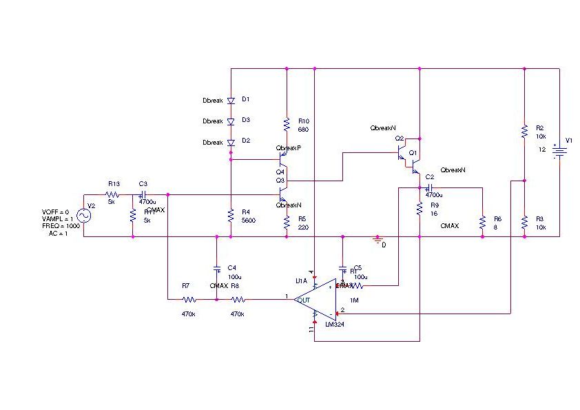
It has a somewhat more evoluted circuit than the previous one. The voltage amplification is realized by a common emitter stage (Q3) which is loaded by a current source stage (Q4, R10, D1-3, R4). This configuration ensures a high linearity minimizing the second harmonic distortion as thoroughly discussed in the (see Bob Cordell site . The power amplification is realized by the common collector stage made with the Darlington Q1(2N3055)-Q2(BC109). Note that the current source load realizes a system of extreme instability which is impossible to bias with conventional trimmers (it can switch from a "biased" condition to saturation or interdiction just with the thermal evolution of the trasistor parameters). It is thus necessary to add an active servo biasing circuit with the op-amp (uA 741 or any other OA) working in open loop configuration and having low pass filters to prevent the alternate signal to reach the input. With the presented values the system takes several minutes to reach stable biasing; I will try to lower the time constants to obtain a more conventional behavior.
 Here you find a modified version that is the final version of this projects:
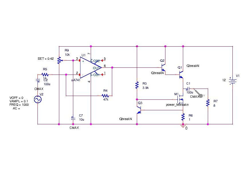 The voltage amplification is realized by an OpAmp (here a TL082): the trimmer must be set in order to have about half of the supply voltage between the BJT and the MOSFET. The final stage has a darlington of BJTs (2N3055+BC109) loaded by a MOSFET constant current source (IRF510). The current is now about 600mA but the same circuit could be used up to several amps. Mind the heat dissipation as already at 600mA it is almost a stove....