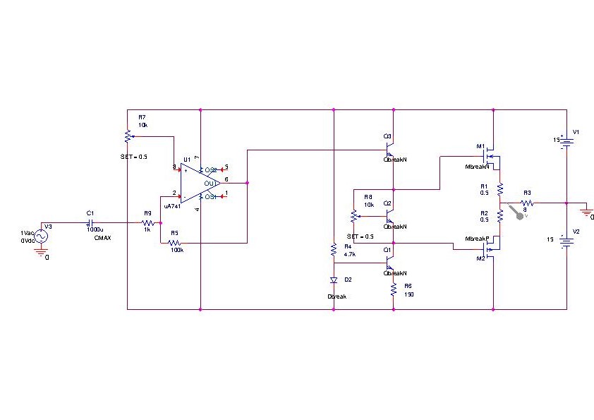
Class AB ampli
Here you find a diagram for a 'Class AB' ampli that I have used for my 5 channels audio surround amplifier. The preamp is realized with a OpAmp (any type would fit, I used TL082 and UA741, OP27 gave me self-oscillation problems), then the signal is sent to a classic "svoltage splitter" stadius that creates two twin signals with about 7V of DC difference that will eventually drive the Mosfet (621, 9621 in the present case) gates. The calibration of the DC levels is quite critical, I recommend +/- 3.5 V (depending on the components slightly higher values could be needed to cancel the crossover distortion) but you're warned that above 4V you seriously risk to make a BBQ rather than a powAmp. A further trick to avoid troubles is to split the power supply in two totally separated (I mean even 2 transformers) circuits: one feeding the preamp, and the other (with a 30sec delayed relay) the mosfets. In this case the power components are powered after the transient at the preamp input giving the DC voltage to enough time reach the correct asymptotic value.
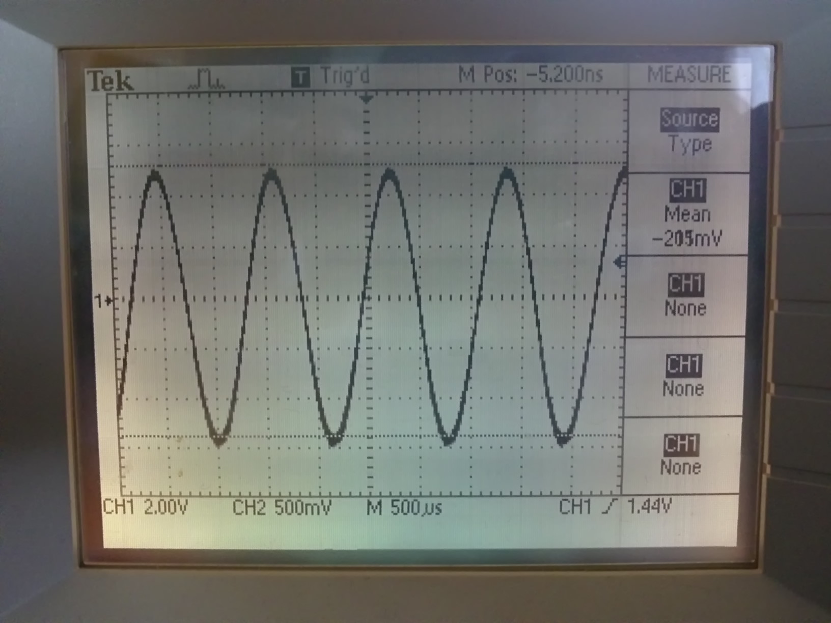
If you calibrate correctly the DC levels you should obtain this quality of signal at the output (12 Ω, resistive load).
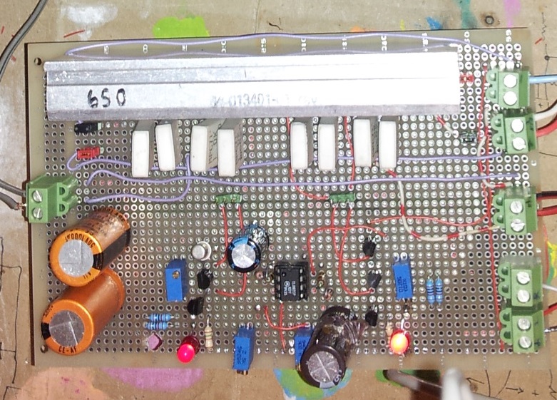
Here you find an image of one two-channels module (got 3 of those ).
BACK
F. d'Acapito, 2014